
Cooling from hot water: how to turn boiler house heat into cooling
In brief. In summer, a boiler house, a heating network or gas engine generator set cooling jackets supply hot water that sits idle. A Thermax absorption chiller turns it into cooling for process needs and air conditioning. We survey the source, calculate the savings, and design and build a turnkey chiller plant. This is how an agricultural complex, a pharmaceutical plant, a research and production company and many other facilities work.
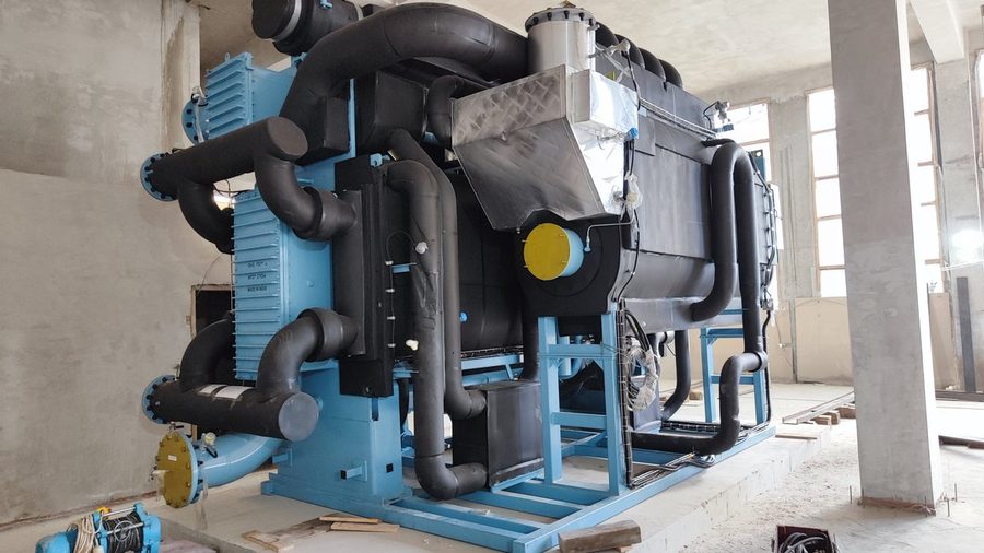
If a facility has hot water available, from its own boiler house, a heating network or the engine cooling jackets of a power plant, it pays to use it for cooling. This is done with hot water-fired lithium bromide absorption chillers. It is one of the absorption cooling schemes we use most often.
When does it pay to use hot water to produce cooling?
When the facility has a heating medium that sits idle in summer or is not fully used: a boiler house, a heating network, the gas engines of its own power plant. An absorption chiller uses this energy instead of electricity and gives noticeable savings on operating costs. This matters most where electrical capacity is short, for example in historic city centers.
Which machine is needed?
We select the machine for the temperature and flow rate of the hot water at the facility. Hot water machines in the 2026 Thermax catalog:
- LT (Cogenie): single-stage machines of small capacity, including for mini CHP plants;
- HS: for medium-temperature water, with minimal electricity use;
- 5G: single-stage machines with the lowest heat consumption in their class;
- 2G: two-stage machines for high-temperature water: the hotter the water, the more cooling each kilowatt of heat gives.
Hot water-fired absorption chiller models, their capacities and coefficients of performance are on abxm-thermax.ru (in Russian).
How does the system work?
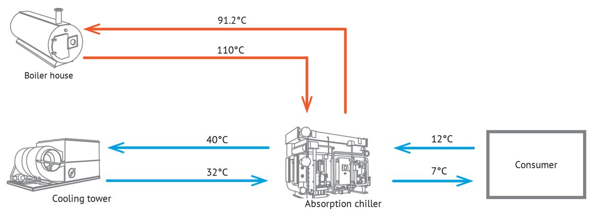
- Hot water from a boiler house or another source enters the absorption chiller.
- In the absorption chiller, the heat of the hot water drives the absorption cycle: heat is taken from the coolant and transferred to the cooling water.
- The chilled coolant goes to the consumer: the air conditioning system or the process.
- The cooling water passes through one or several wet cooling towers and returns to the machine.
The hot water can come from any source, from domestic hot water networks to geothermal sources.
Which schemes are used most often?
Hot water from the facility's own boiler house. The boiler house supplies water to the absorption chiller, and the cooling towers reject the heat.
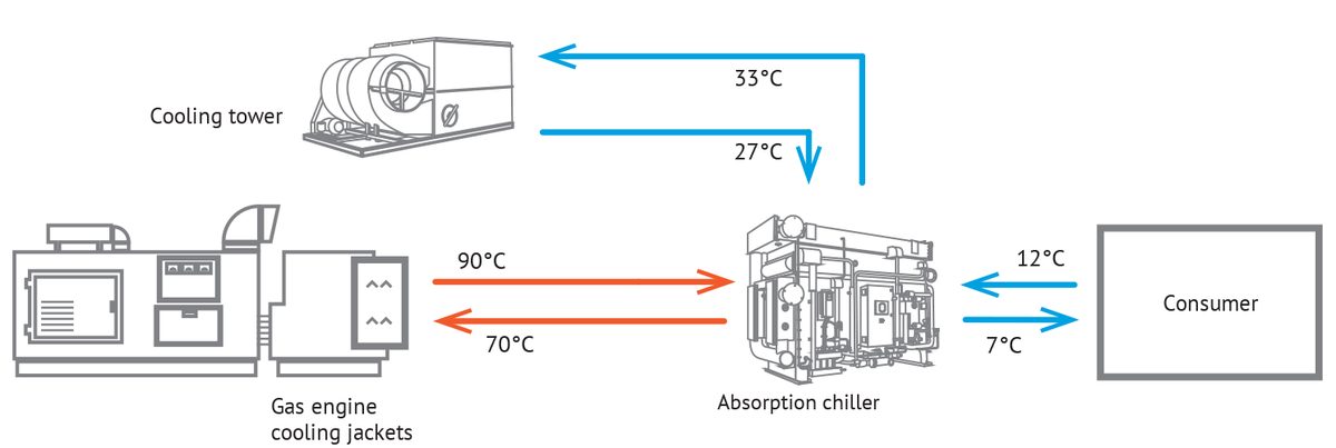
Hot water from gas engine cooling jackets. Heat that the power plant would otherwise release to the atmosphere is turned into cooling. Such a system produces electricity, heat and cooling at the same time; this is trigeneration.
What equipment does the system include?
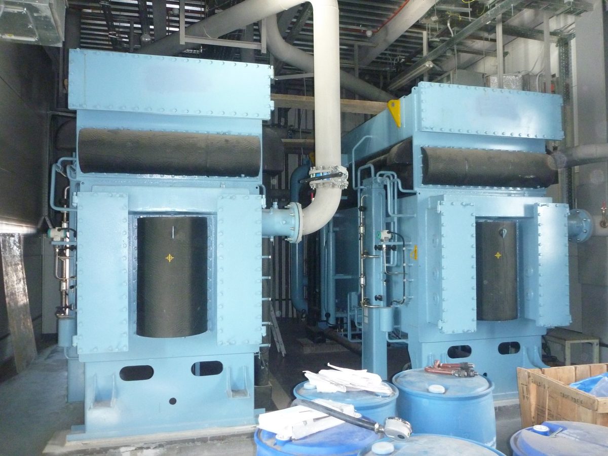
- Hot water-fired Thermax absorption chillers. Since 2011, we have been the official and exclusive representative of Thermax in Russia and the CIS.
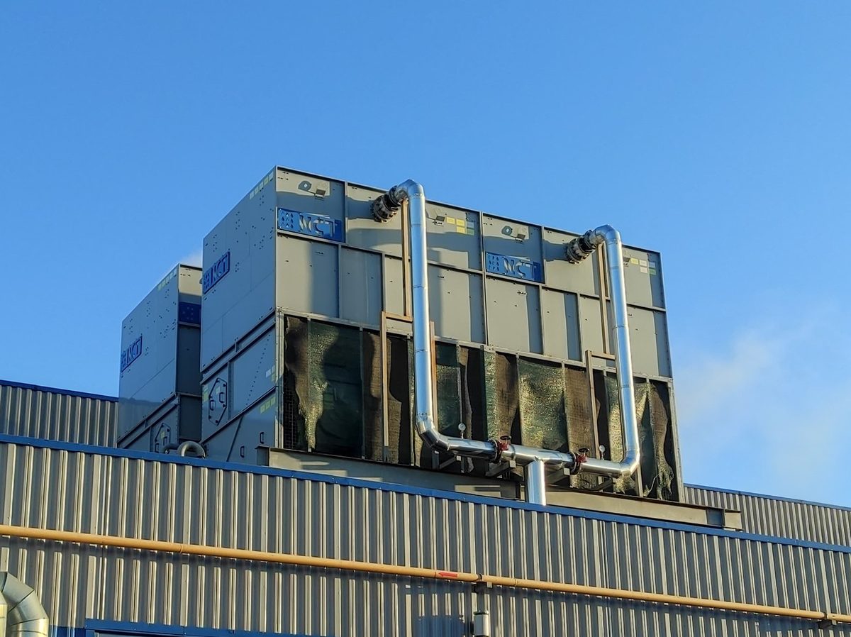
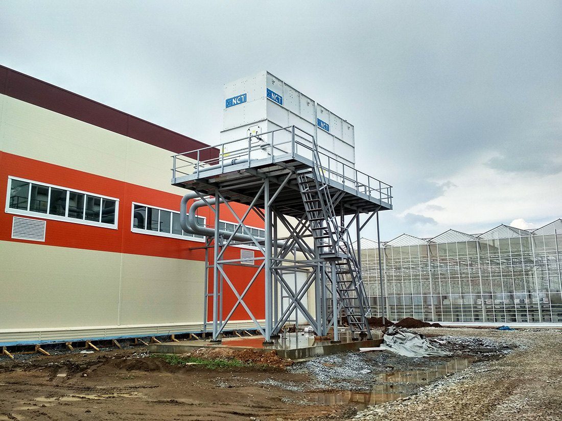
- NCT cooling towers of our own manufacture for cooling the absorption chillers.
- NCT pump skids and chemical water treatment systems.
- A control system.
Which facilities operate on this scheme?
- Vyborzhets agricultural complex (in Russian), Leningrad Region: two Thermax 5G absorption chillers with a total capacity of 3.8 MW on 120/60 °C hot water, two NCT VR4 cooling towers. An energy center with GE Jenbacher and MWM gas engine generator sets.
- Aktivny Komponent (in Russian), Leningrad Region: two 1,430 kW absorption chillers running on water from the cooling jackets of Jenbacher gas engines cool the process lines and premises.
- Central Customs Administration (in Russian), Moscow: two 500 kW absorption chillers on hot water from a boiler house and microturbine heat recovery boilers. The machines are installed in the basement of a historic building.
- Döhler food ingredients plant (in Russian), Lobnya: a 1,500 kW absorption chiller running on gas engine heat cools water from 14 to 0 °C for the pasteurizers.
- Mikran plant (in Russian), Tomsk: two 1,100 kW absorption chillers on hot water from a gas engine plant.
- Metrostroy sports complex (in Russian), St. Petersburg: two 5G 3M C absorption chillers, 1.85 MW in total, on water from a stand-alone boiler house: in winter it heats the building, in summer it supplies heat to the machines. Cooling here costs 3–4 times less.
- Smolensk Academy of Physical Culture and Sports (in Russian): two 5G 4L C absorption chillers, 2.2 MW in total, on hot water from the academy's own boiler house.
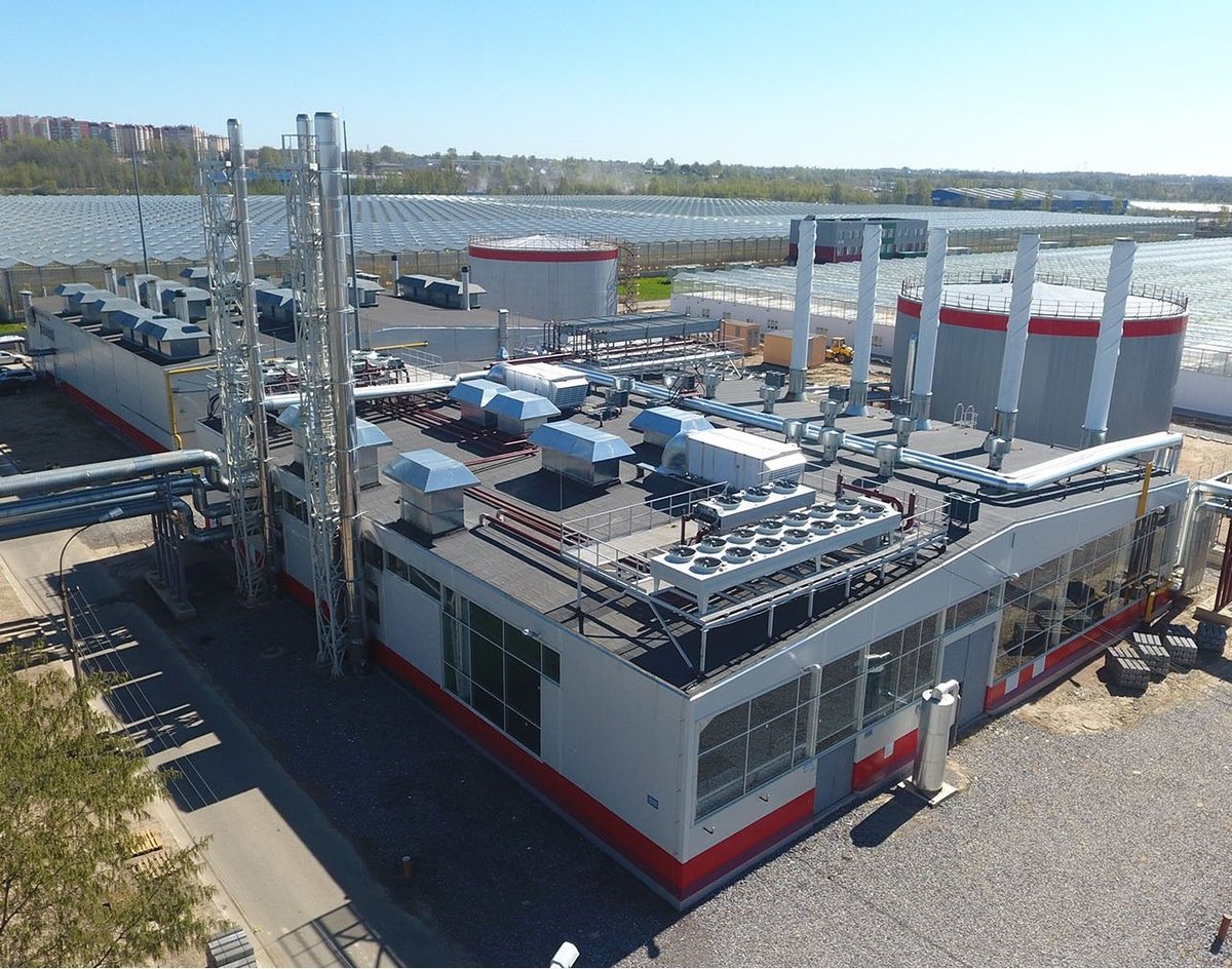
Selected projects are in the Projects section.
What do customers say?
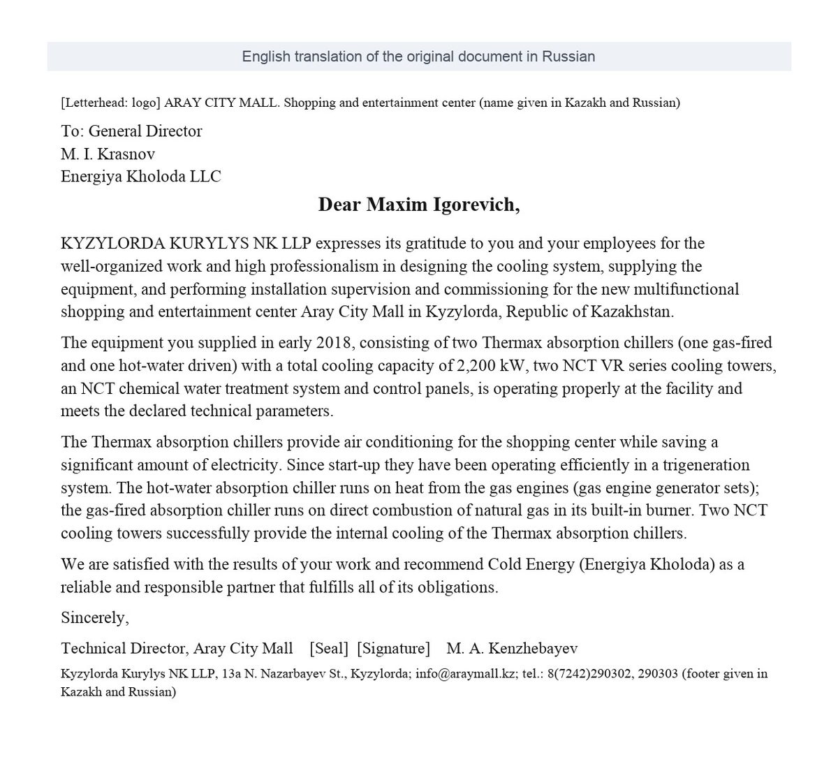
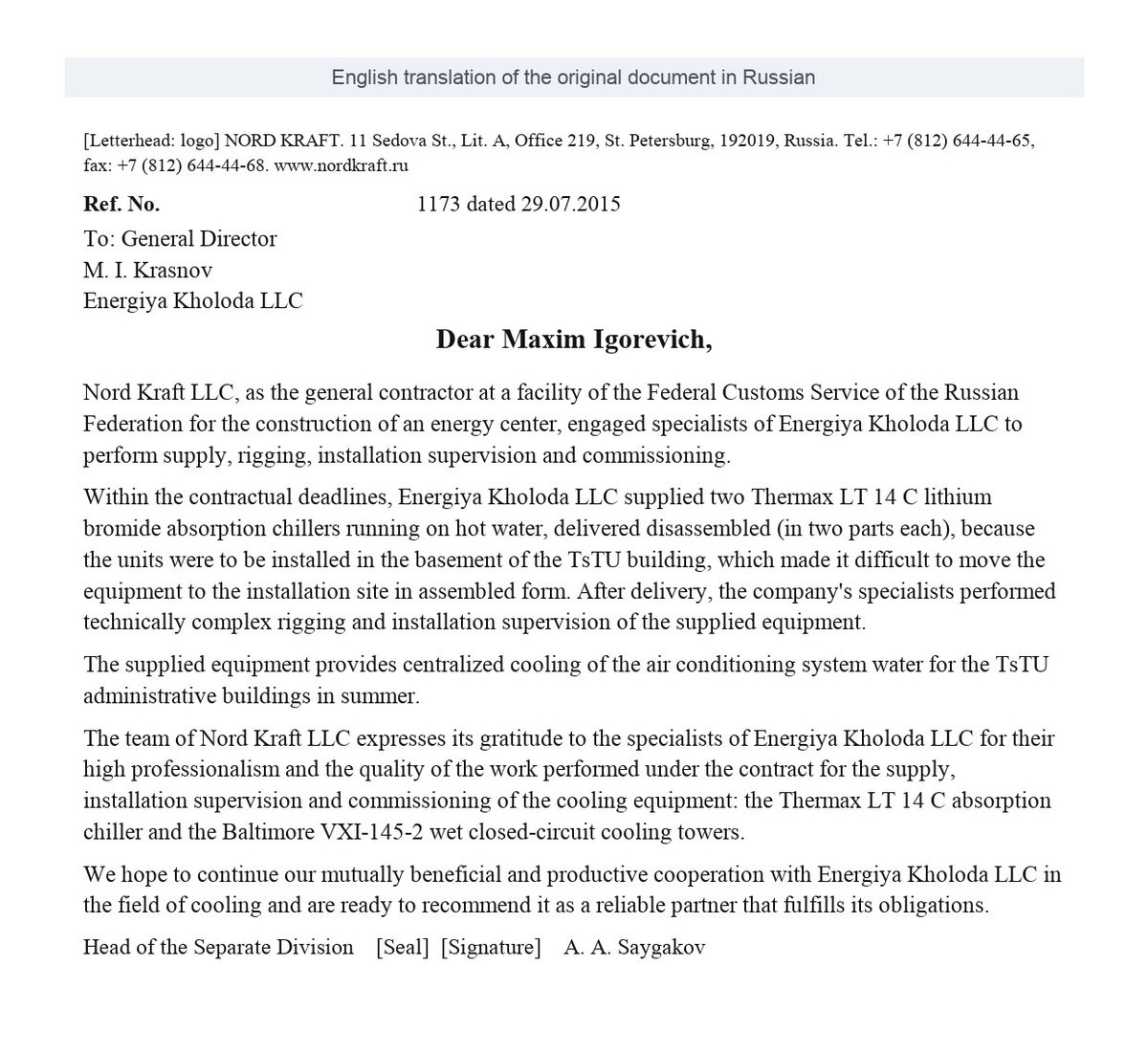
All reviews are on the Reviews (in Russian) page.
How does a project run?
- Engineer consultation: we study the hot water source and the cooling demand.
- Concept, layout options and a feasibility study.
- Design at our engineering center.
- Equipment supply, installation supervision and commissioning.
The consultation, layout options and feasibility study are free of charge.
Resources
- All about Thermax absorption chillers (in Russian)
- Heat recovery: absorption chillers and absorption heat pumps
- The guide "Absorption chiller or electric chiller: 1,000 kW cost comparison" can be sent to you by email or Telegram: get it on the guide page. Inside: a three-step quick choice, the limitations of absorption chillers and the numbers: on cheap heat, a 1,000 kW machine saves about RUB 1.02 million a year.
Cooling schemes
The hot water connection to the absorption chiller is shown in the diagrams above. Below, for comparison, are typical schemes for absorption chillers with other heat sources: steam and natural gas. The numbers on the diagram are the piping components; the key is under each diagram.
Alternative: steam-fired absorption chiller
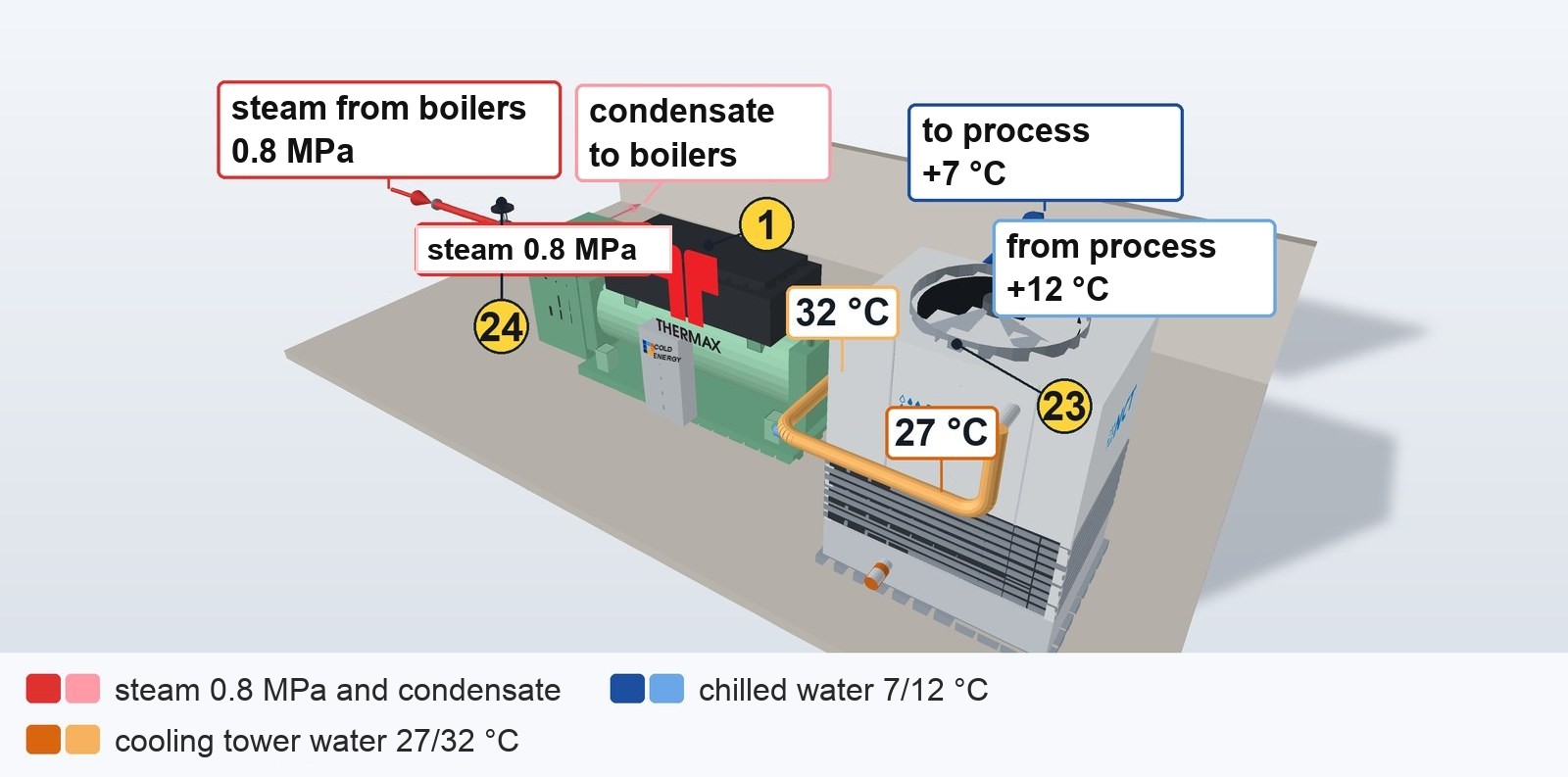
Steam heats the machine's generator, chilled water goes to the process, and the heat of absorption goes to the cooling tower.
Key to the numbers on the diagram
| No. | Component | Purpose |
|---|---|---|
| 1 | Steam-fired Thermax absorption chiller | steam heats the solution, and the machine delivers chilled water without a compressor |
| 23 | NCT cooling tower | rejects the heat of absorption: there is more of it than from a compressor machine of the same capacity |
| 24 | Steam control valve | meters the steam according to the load: the machine holds +7 °C at the outlet |
Alternative: direct-fired natural gas absorption chiller
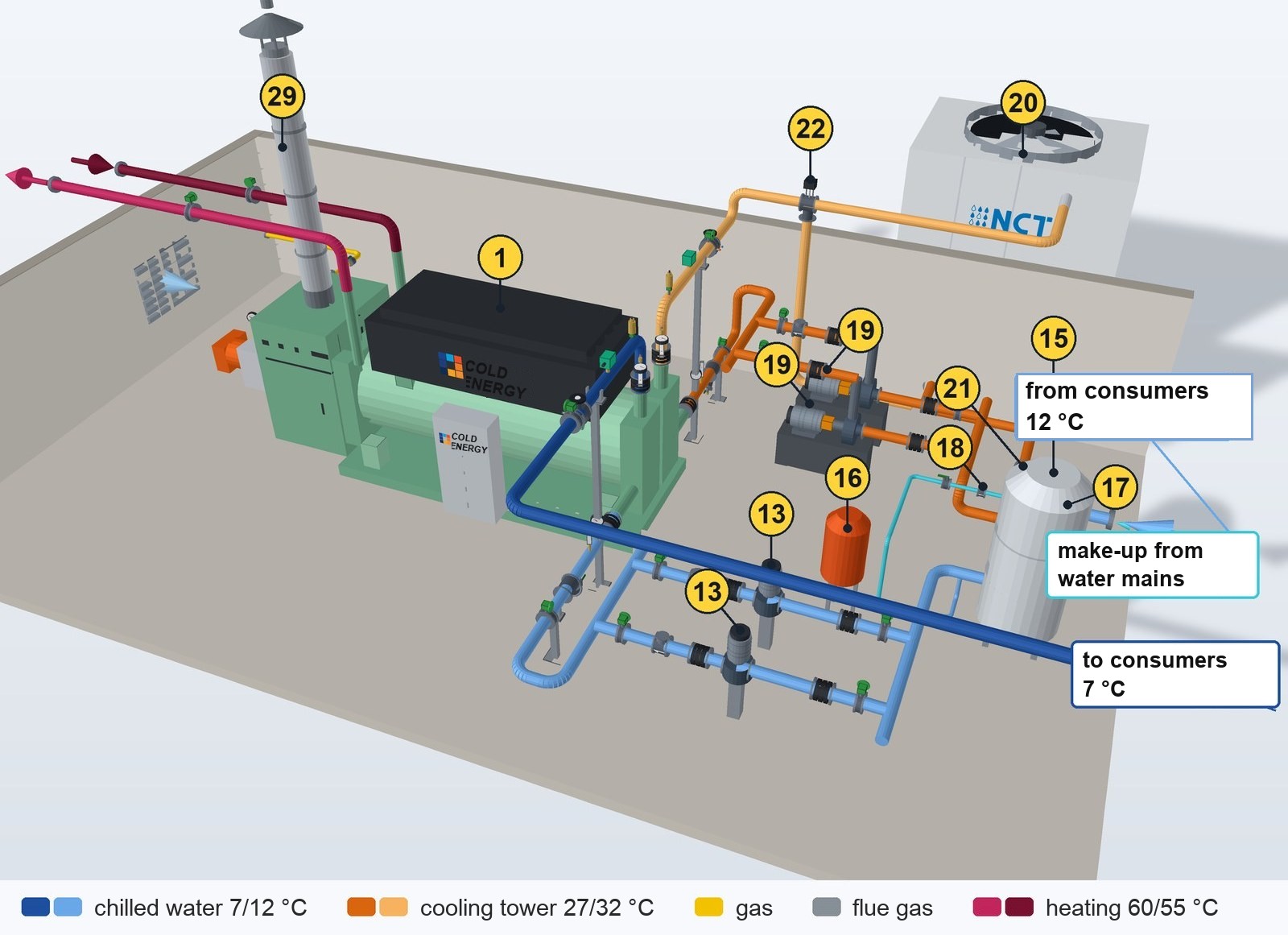
Gas goes through the gas train to the burner, flue gas goes to the stack; chilled water goes to the consumer, cooling tower water passes through the absorber and the condenser, and in winter hot water can be taken for heating.
Key to the numbers on the diagram
| No. | Component | Purpose |
|---|---|---|
| 1 | Direct-fired absorption chiller (gas) | cooling from the heat of gas combustion; the refrigerant is water, the absorbent is lithium bromide |
| 3 | Butterfly valve | isolates the machine and pumps for repair and flushing; installed in pairs, inlet and outlet |
| 4 | Y-strainer | catches scale and debris before the unit's tubes; on the INLET only |
| 5 | Flexible connector (vibration isolator) | right at the nozzle: damps vibration, does not transfer the pipe's weight and misalignment to the nozzle |
| 6 | Thermometer in a thermowell | inlet and outlet temperature: the difference shows the load |
| 7 | Pressure gauge with a valve | pressure before and after: the pressure drop = flow and tube fouling |
| 8 | Drain valve | drains water from the unit and the circuit; at the lowest point |
| 9 | Pipe support | carries the weight of the pipe and valves: the machine's nozzle is not loaded |
| 10 | Automatic air vent | at the highest point: releases air (noise, corrosion, pump cavitation) |
| 11 | Flow switch | no flow means the machine is not allowed to start; a paddle switch needs straight runs of ≥5 DN |
| 12 | Balancing valve | sets the design flow through the unit; the test points are for the instrument |
| 13 | In-line pump | circulates water through the circuit; in a pair, duty + standby |
| 14 | Check valve | prevents water from flowing back through the idle pump |
| 15 | Buffer tank | a reserve water volume: the machine does not cycle on and off often |
| 16 | Diaphragm expansion tank | takes up the expansion of the fluid when heated and holds the pressure at the pump suction |
| 17 | Make-up assembly: valve | circuit make-up; the valve is for manual shut-off |
| 18 | Make-up assembly: backflow protection (shown on the drawing as a check valve for simplicity) | the circuit fluid must not get into the drinking water supply: one ordinary check valve is not enough; a double check valve, a reduced pressure zone (RPZ) valve or an air gap is needed; with glycol or chemicals, only an RPZ valve or an air gap; the type is set by the water utility's technical conditions |
| 19 | End-suction pump (duty + standby) | axial inlet, top outlet; the motor is on a common baseplate |
| 20 | NCT open cooling tower | cools the water by evaporating part of it into the air |
| 21 | Coarse screen at the cooling tower pump suction | protects the pump from leaves and large debris: 4.8–6.4 mm mesh, low pressure drop, a screen at the basin outlet is better; a fine strainer is not installed on the suction, it goes after the pump and at the condenser inlet (component 4) (B&G TEH-1209A, pp. 14–16) |
| 22 | Cooling tower three-way bypass valve | sends part of the water past the cooling tower: the water to the machine is not overcooled (for an absorption chiller, there is a risk of crystallization) |
| 23 | Gas train: ball valve | manual gas shut-off at the gas train inlet |
| 24 | Gas train: gas filter | traps dust and scale; otherwise the valves will not close tightly |
| 25 | Gas train: pressure gauge / pressure switch | gas pressure monitoring; the min./max. pressure switches are part of the burner protection |
| 26 | Gas train: pressure regulator | reduces the gas pressure to what the burner needs and keeps it constant |
| 27 | Gas train: two solenoid valves | double shut-off: the gas closes instantly in an emergency or if the flame goes out |
| 28 | Gas burner | burns gas in the high-temperature generator |
| 29 | Insulated flue | carries the flue gases above the roof; the insulation protects against burns and condensation |
| 30 | Combustion air intake louvers | the burner needs air: without an air supply, the room will run short of oxygen |
Frequently asked questions
In summer, the heating medium is only about 75 °C. Will the machine work on such water?
It will, but the capacity will be noticeably below the rated value. The LT series works from 70 °C and is economically justified from 80 °C. Calculate the actual summer supply and return temperatures, not the schedule in the contract with the heating network. In one project, after checking them, the customer chose a direct-fired gas machine. The factory makes the selection for your conditions based on the supply and return temperatures and the flow rate.
Can a hot water-fired absorption chiller produce very cold water, around +3 °C?
It can, but only to special order. Standard LT and 5G go down to 3.5 °C; for +3 °C the factory selects the machine individually: not from stock, possibly with a different tube material, at a higher price and weight. First check that the process really needs +3 °C: at +5…+7 °C you get a wider pick and easier lead times. With glycol on hot water the catalog gives down to −2 °C; −5 °C is the limit for gas-fired and steam machines, below that only a compressor works.
Are storage tanks needed in the chilled water and hot water circuits?
In most cases, no. With a 7/12 °C schedule, smooth machine modulation, a large system volume and an even load, a tank is not needed. They are usually not installed in the hot water circuit either; just do not confuse them with expansion tanks: those are always needed, and their volume is calculated from the system and the temperature difference. The exception is a load with peaks. At a dairy plant, the machine stores ice water during quiet hours for the next peak.
We will calculate the system for your facility free of charge: submit a request or call +7 (800) 333-49-96.
Let us size a cooling system for your site
An engineer will select the equipment and send you a calculation. Free of charge, no obligation.